For switching devices not specifically designed to this application, such as traditional circuit breakers and vacuum switches, energizing capacitor banks can result in harmful overvoltage and overcurrent transients. Deenergizing capacitor banks can also result in restrikes that can damage the capacitor bank, switching device and other system components.
In the paper “Pre-insertion Resistors in High Voltage Capacitor Bank Switching,” presented at a conference in Seattle, the co-authors write, “The engineer’s goal is to control, limit, and direct transient currents so that adverse effects on the source system, the capacitors, their switching devices, and associated equipment are limited to acceptable values.” This excerpt explains it well. As suppliers of power, thoughtful consideration must be given when choosing the right solution for your system and application.
Application: Capacitor Switching Considerations
Minimize or Eliminate Harmful Transients When Energizing Capacitor Banks
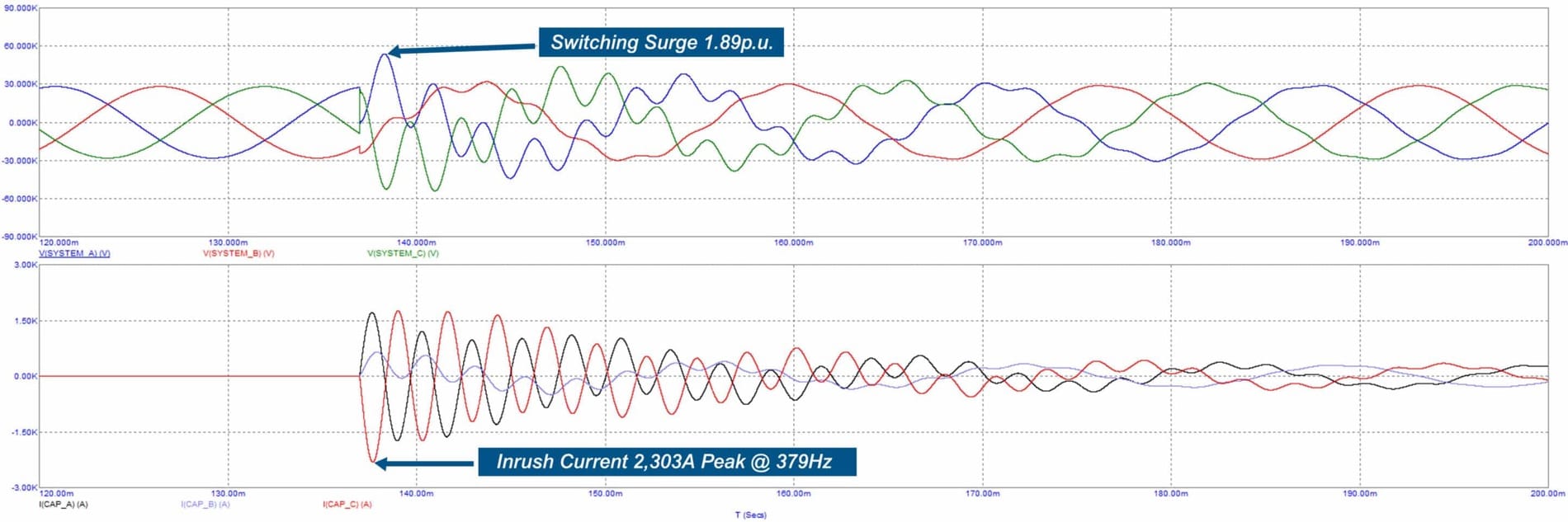
Capacitor energization transients are created by the effective short circuit provided by a discharged or insufficiently discharged bank during energization. This “short circuit” results in a high frequency and magnitude inrush current as the system rapidly charges the capacitor bank to equalize the system and capacitor voltage. This inrush current causes a voltage dip at the capacitor bus followed by an overshoot in voltage that can approach 2 per unit. These voltage transients aren’t usually harmful to utility equipment but in the presence of certain system configurations or sensitive loads can result in equipment shutdown or failures.
Single Capacitor Bank Switching (click photo to expand)
Back to Back Capacitor Bank Switching (click photo to expand)
Minimize or Eliminate Restrikes When De-Energizing Capacitor Banks
As shunt capacitor banks are switched out (de-energized), restrikes and reignitions can occur when the dielectric strength of the open gap, during contact parting, is not great enough to withstand the recovery voltage. This can cause a premature resumption of current flow, leading to cascading over-voltages than can cause ruptured capacitor cans, blown fuses, failed arrestors, external equipment flashovers, and contact wear that may lead to interrupter dielectric failures.
Methods of Capacitor Switching & Related Devices
As we just learned, shunt capacitor bank switching requires the designer to take into consideration the unique system response that occurs when switching capacitor banks. There have been many different approaches taken to minimize the impact of increased switching of capacitor banks. These include adaptations of general-purpose switching devices such as circuit breakers as well as specific-purpose switching devices. The following is a brief review of some of those approaches:
1) Arrestors
Surge arrestors, also called surge protection devices, are used to minimize the probability of multiple restrikes once a restrike has occurred.
2) Series (Inrush or Current-Limiting) Reactors
Full time inrush reactors are chosen to limit inrush currents below the damage levels of the switching device and other components in the capacitor bank (fuses, current transformers, etc.). Although effective for reducing the transient inrush current, they are not effective in reducing the overvoltage transient, and they are always energized producing losses from its resistance. Under certain fault conditions, the high rate of rise of the TRV, caused by the reactor, may make it very difficult for the switching device to clear the circuit.
3) Controlled Switching (Zero-Voltage or Synchronous Controls) for General-Purpose Breakers
This method reduces magnitudes of energization transients by utilizing complex controls that attempt to close the switching device at a point when the system voltage is near zero. Controlled voltage switching can be very effective, but complicated electronics are required in the attempt to manage the natural mechanical scatter and wear of the switching device and changes in ambient temperature and control voltage. Maintaining this system to achieve adequate reliability can be very costly and adversely affect capacitor bank availability.
On back-to-back capacitor switching applications, current limiting reactors are still required because just one failure of the switching device to close on a zero voltage can severely damage the switching device and the capacitor bank.
4) Pre-Insertion Inductors/Reactors
This two-stage device momentarily introduces—and then quickly shorts out—an inductance. The inductor is chosen to reduce the initial transient when energizing the capacitor bank and attempts to balance the inrush events between the insertion and bypass of the inductor. Although this approach can be effective, the methodology essentially eliminates the ability of the switching device to close into a fault. Also, in the designs available on the market, the stationary and moving arcing contacts are exposed to the elements and require maintenance.
5) Pre-Insertion or Closing Resistors
Pre-insertion of a properly sized resistance, for a short time during energization, effectively reduces the inrush current while the capacitor charges to attain system voltage, minimizing its overshoot. Along with sizing the resistor to minimize the overcurrent and overvoltage transients, they need to be adequately sized for the anticipated switching duty and to close into a fault without damage to the switching device.
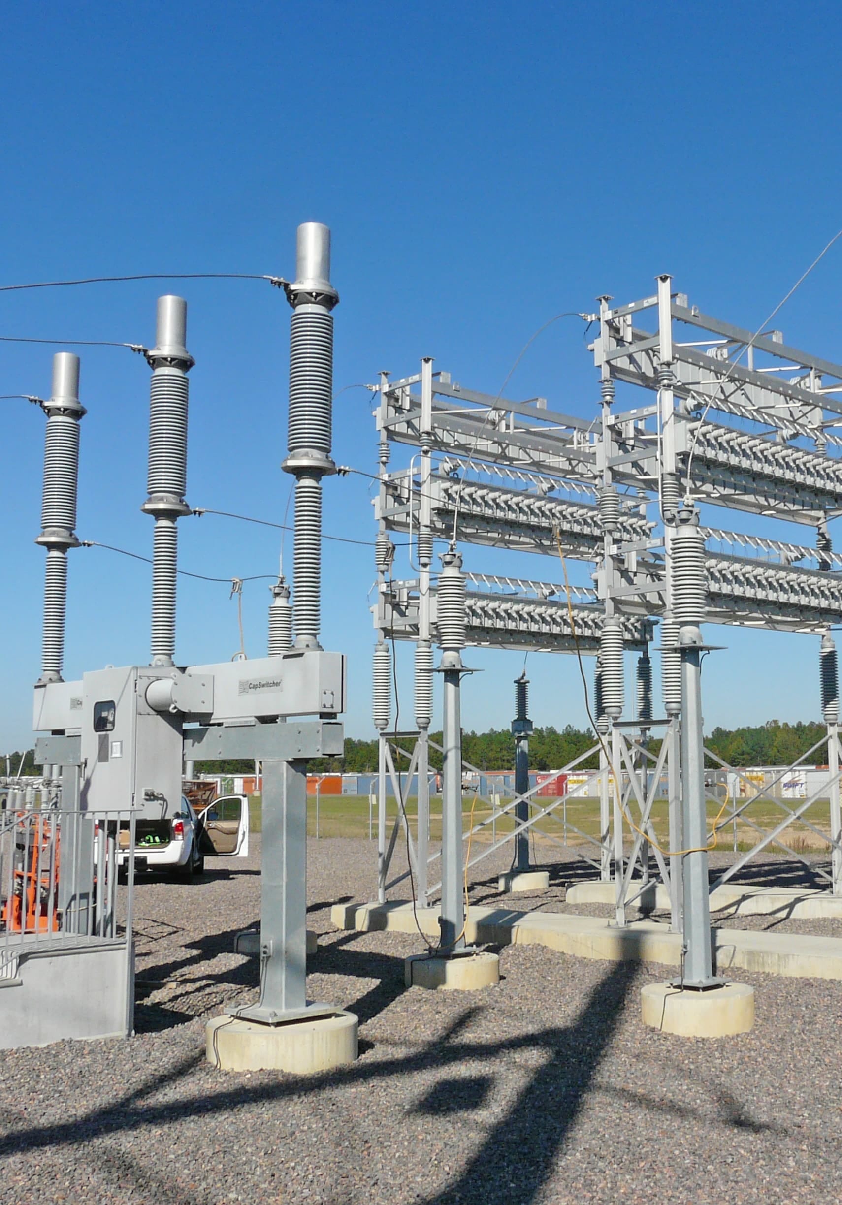
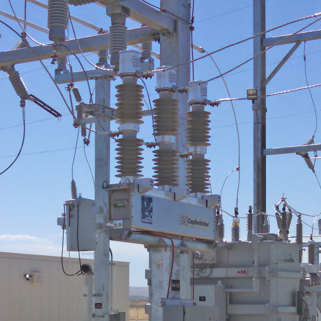
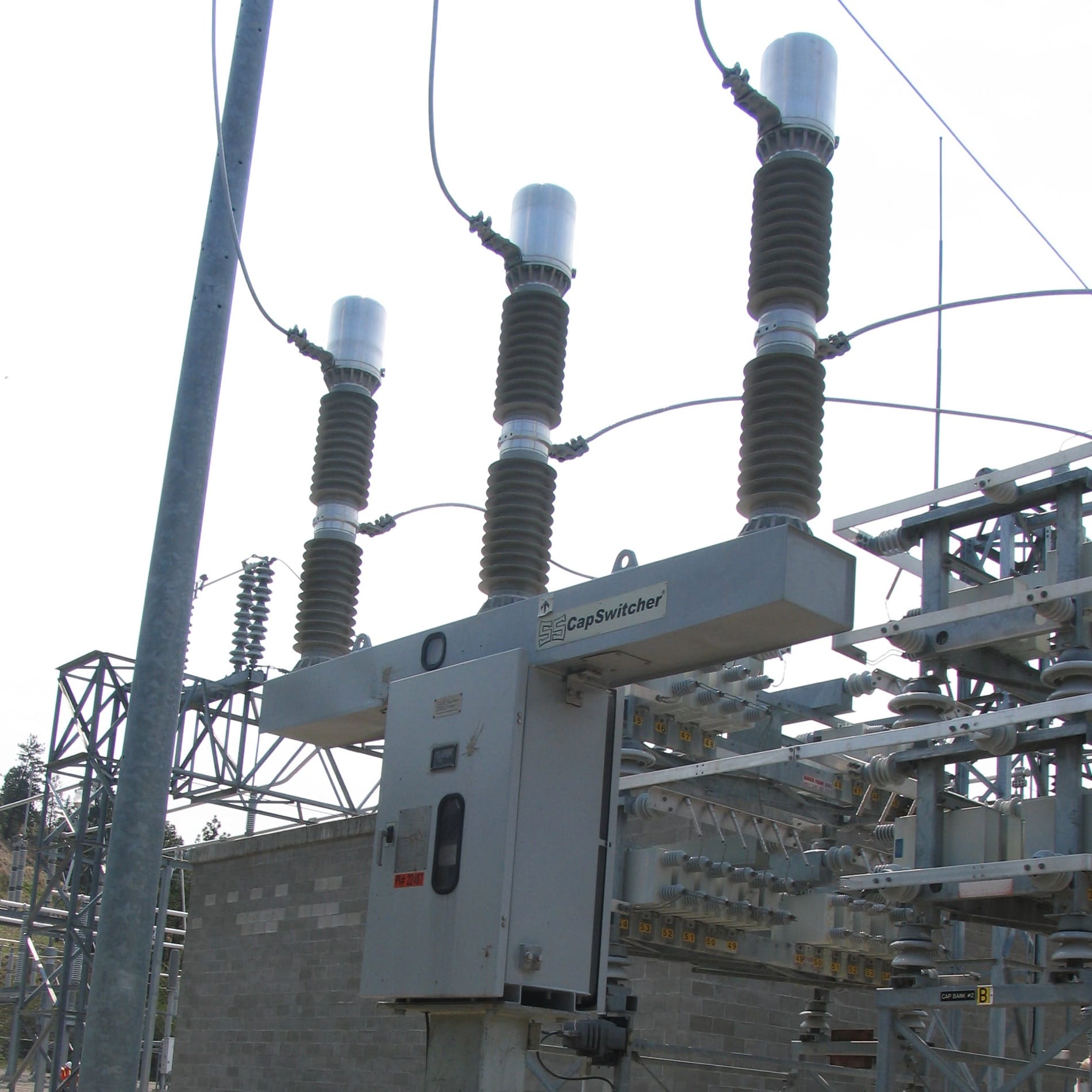
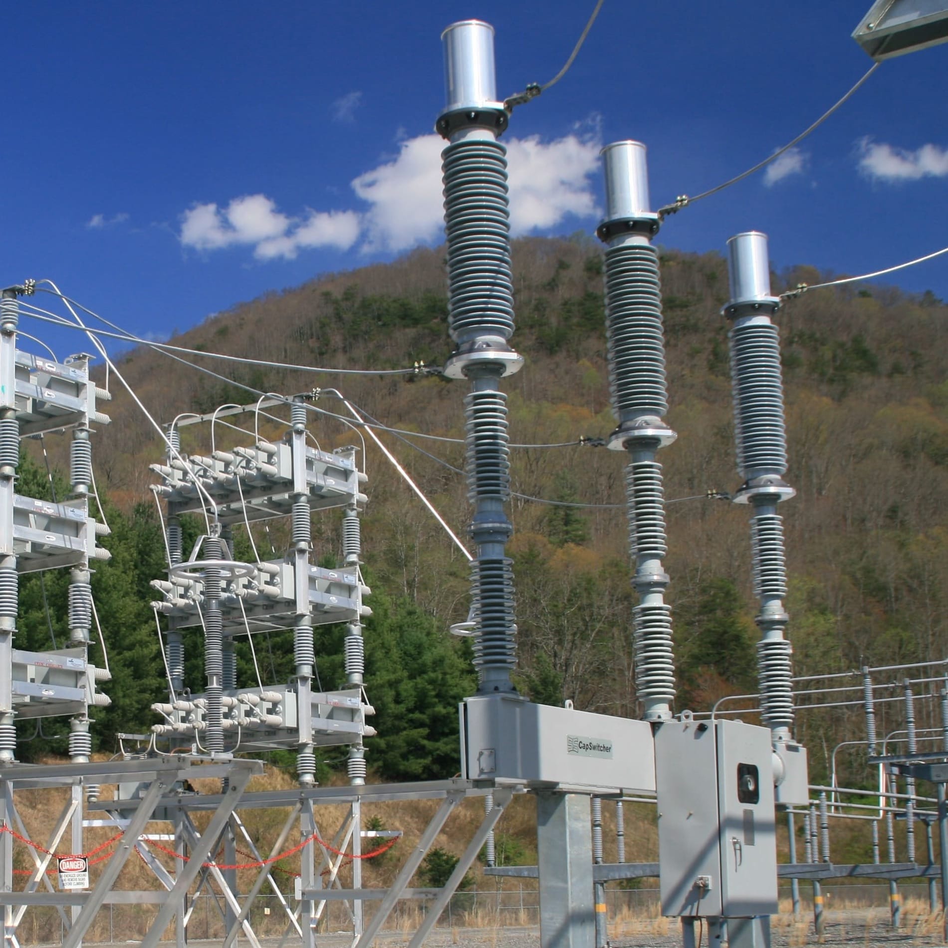
Southern States CapSwitcherⓇ
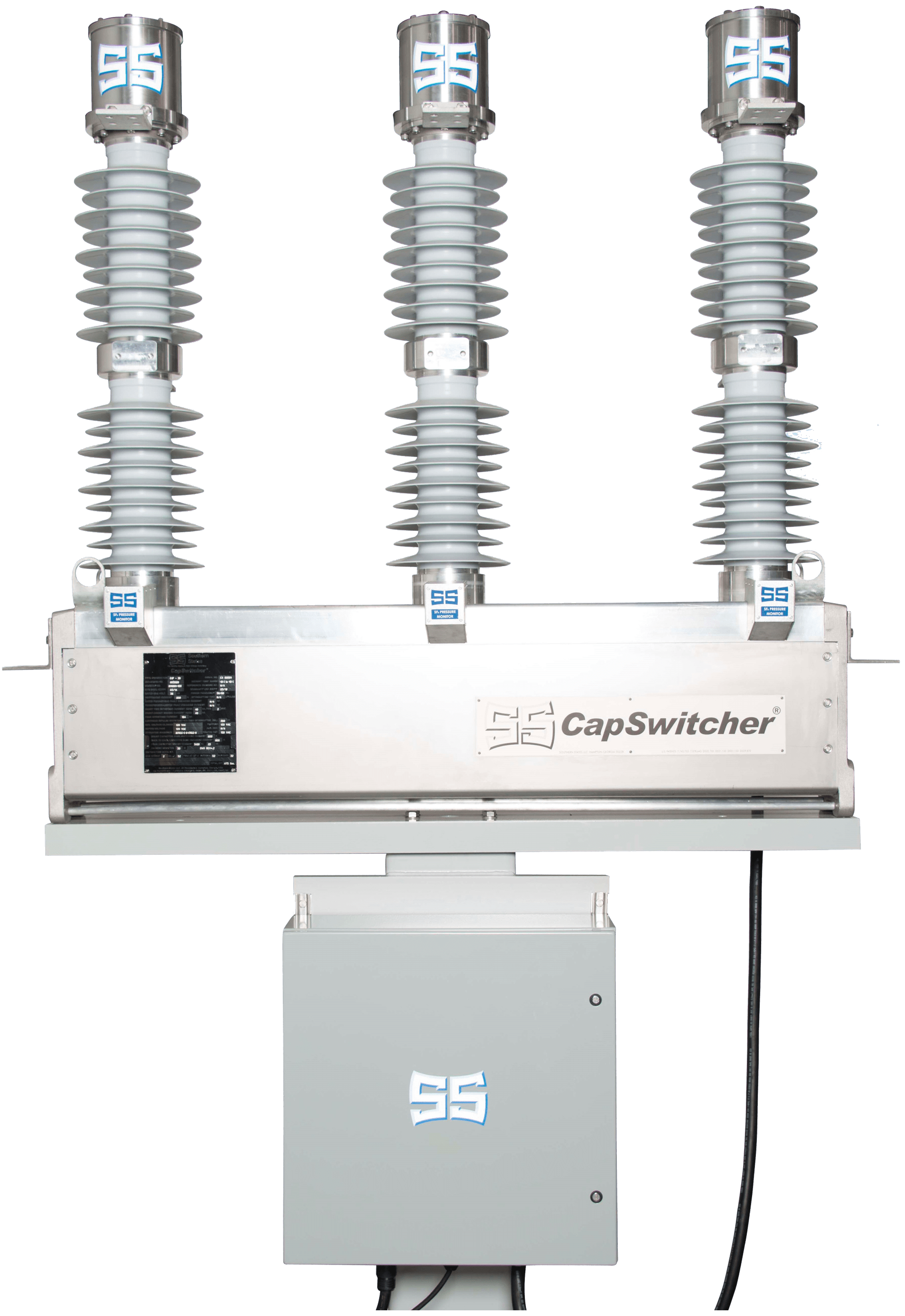 The Southern States CapSwitcherⓇ is the only switching device designed specifically for capacitor switching. Launched in 2003, this special-purpose switching device works well with medium and high-voltage capacitor banks and can be used in single bank or back-to-back bank applications. The CapSwitcher was designed to meet modern power quality needs—and built for long-term use, capable of handling 10,000 operations.
How Our CapSwitcherⓇ Works
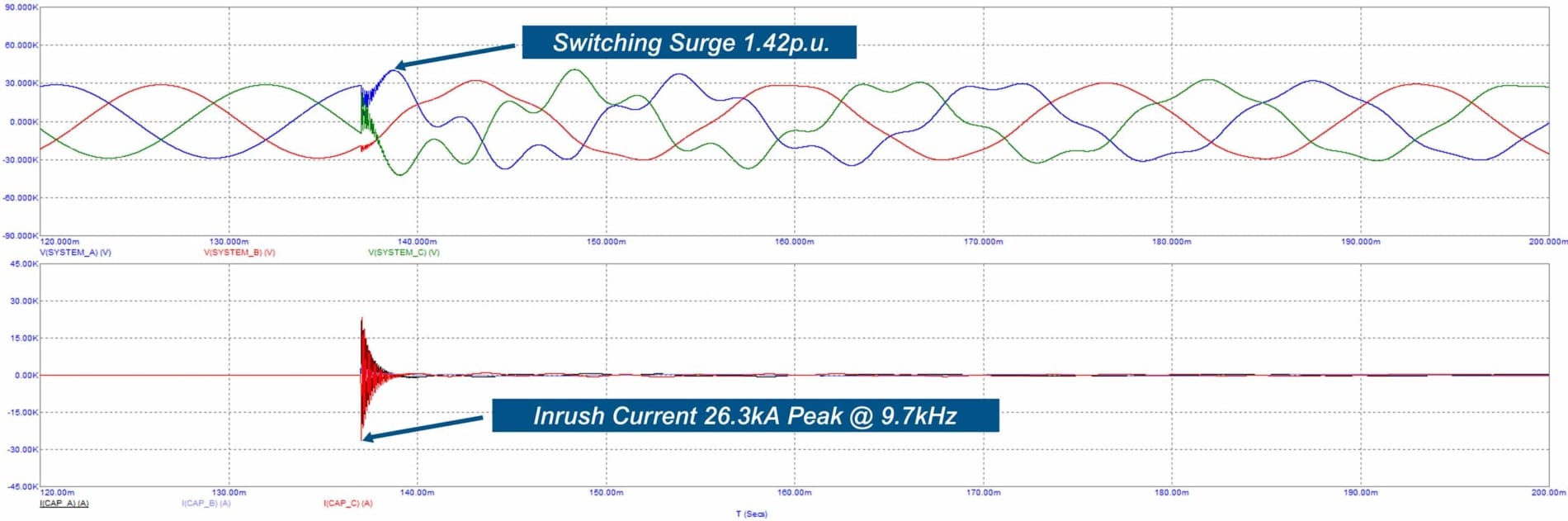
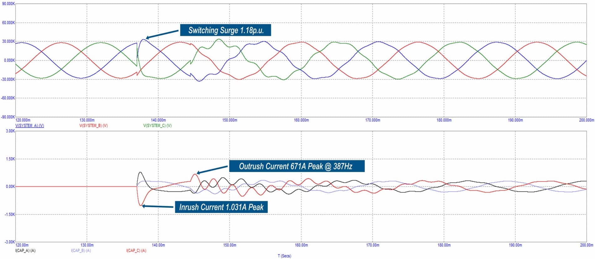
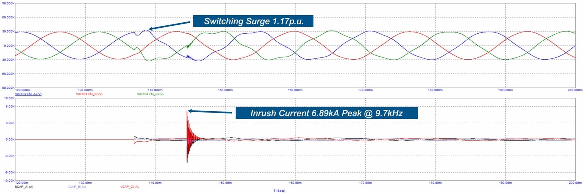
Our CapSwitcher is a two-stage switching device that momentarily introduces resistance into the circuit when energizing a capacitor bank. Upon receiving a closing command, the moving contact energizes the capacitor bank through a closing resistor. Then, the moving contact engages a fixed main contact that shunts the closing resistor. With properly sized closing resistors, voltage transients and inrush currents are reduced. This minimizes disturbances and protects equipment from exposure to damaging transients during capacitor bank switching.
To interrupt the circuit, the CapSwitcher uses a true SF6 puffer designed to ensure restrike-free switching of the capacitor bank.
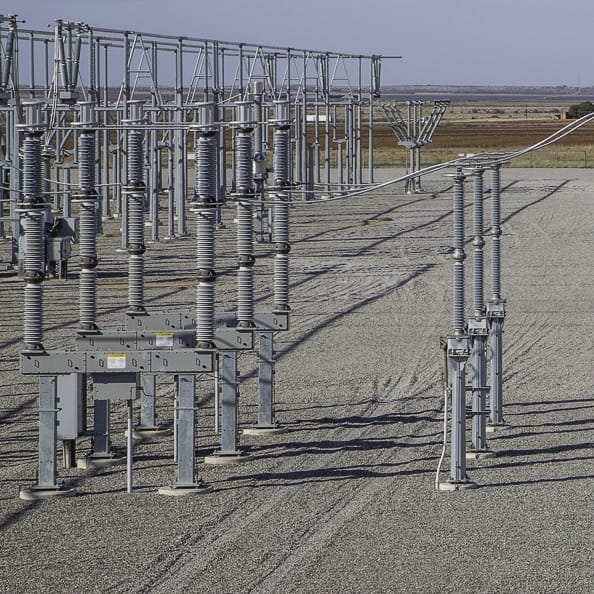
Single Capacitor Bank Switching Using CapSwitcher Technology (click photo to expand)
Back to Back Capacitor Bank Switching Using CapSwitcher Technology (click photo to expand)
Benefits of the Southern States CapSwitcherⓇ
Our product’s intentional design offers many advantages over a general-purpose switching device. Here’s a look at the features of our CapSwitcherⓇ
- Mechanical design does not require point-on-wave switching
- Closing resistors mitigate voltage and current transients
- Various resistor sizes allow optimization for best results
- No need for inrush reactors
- Most models include interrupting capability
- Makes and breaks circuits in gas rather than air
- Fault close ratings on all models
- Virtually eliminates restrikes
- Low-maintenance design
- Built for a long life—up to 10,000 operations
- Provides gas monitoring
How Our CapSwitcherⓇ Works
Our CapSwitcher is a two-stage switching device that momentarily introduces resistance into the circuit when energizing a capacitor bank. Upon receiving a closing command, the moving contact energizes the capacitor bank through a closing resistor. Then, the moving contact engages a fixed main contact that shunts the closing resistor. With properly sized closing resistors, voltage transients and inrush currents are reduced. This minimizes disturbances and protects equipment from exposure to damaging transients during capacitor bank switching.
To interrupt the circuit, the CapSwitcher uses a true SF6 puffer designed to ensure restrike-free switching of the capacitor bank.
Single Capacitor Bank Switching Using CapSwitcher Technology (click photo to expand)

Back to Back Capacitor Bank Switching Using CapSwitcher Technology (click photo to expand)
Benefits of the Southern States CapSwitcherⓇ
Our product’s intentional design offers many advantages over a general-purpose switching device. Here’s a look at the features of our CapSwitcherⓇ
- Mechanical design does not require point-on-wave switching
- Closing resistors mitigate voltage and current transients
- Various resistor sizes allow optimization for best results
- No need for inrush reactors
- Most models include interrupting capability
- Makes and breaks circuits in gas rather than air
- Fault close ratings on all models
- Virtually eliminates restrikes
- Low-maintenance design
- Built for a long life—up to 10,000 operations
- Provides gas monitoring
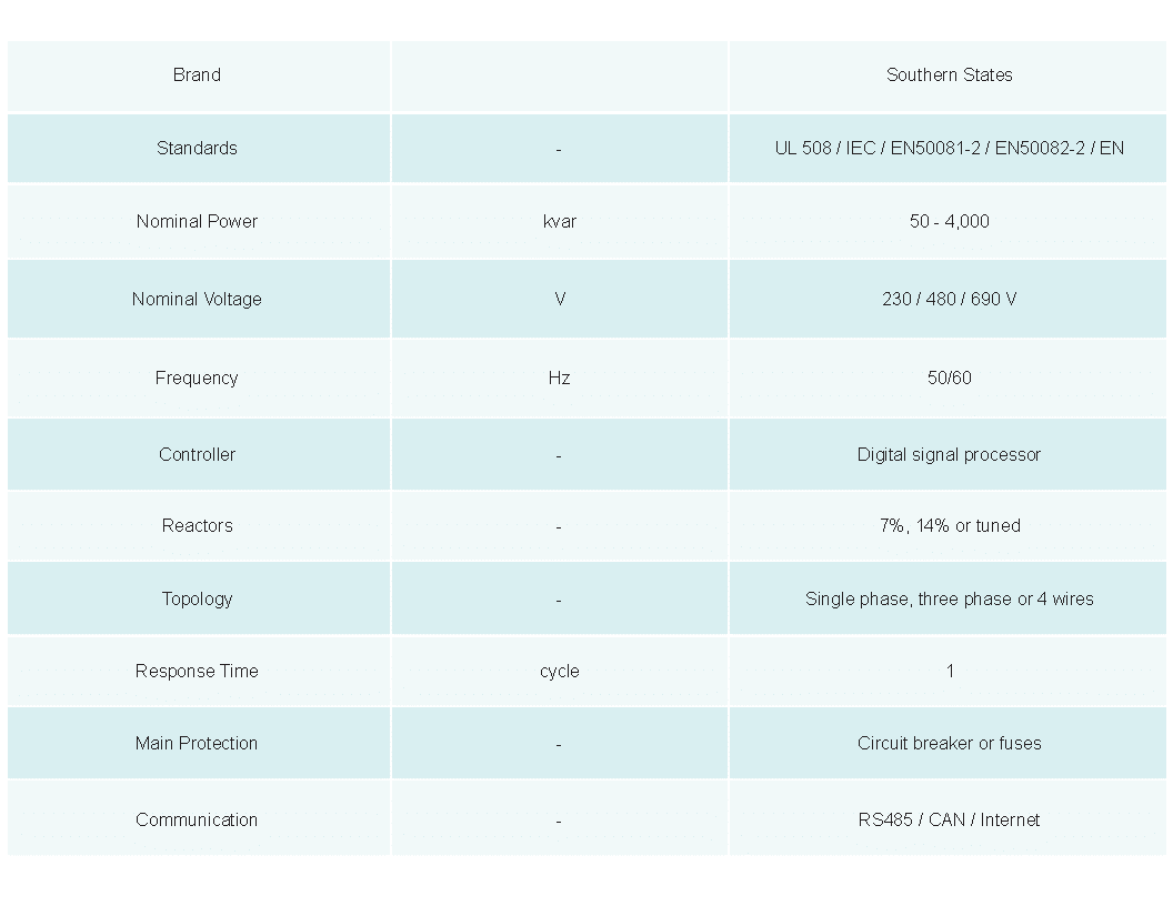
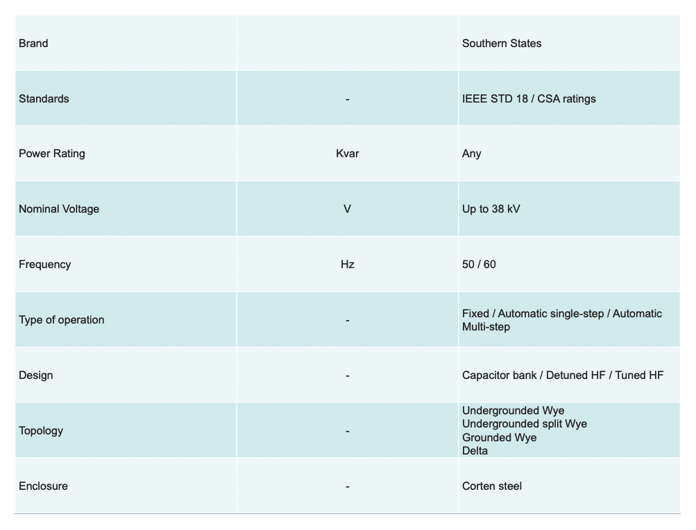
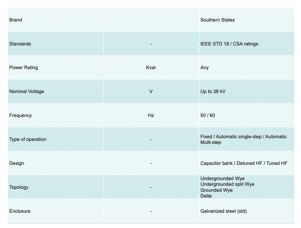
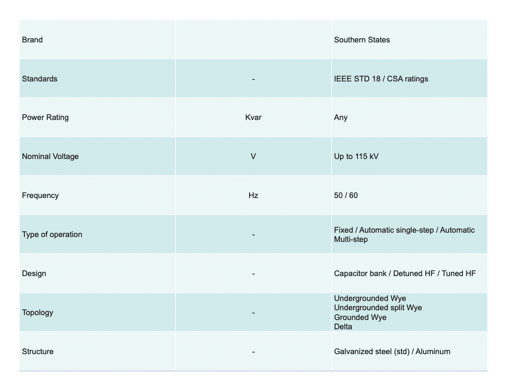
Product Offerings
Southern States offers the CapSwitcherⓇ for several system applications to meet the varying power needs of utility providers. These include maximum voltage ratings of:
Product Offerings
Southern States offers the CapSwitcherⓇ for several system applications to meet the varying power needs of utility providers. These include maximum voltage ratings of:
Capacitor Switching Frequently Asked Questions
Here are a few quick answers for some common capacitor switching questions.
What Is Capacitor Switching?
What Are Typical Applications for Capacitor Banks?
What Is Reactive Power?
What Is Reactive Power Compensation?
Resources
- Capacitor Switching Catalog Bulletin
- Capacitor Switching Compendium – Design Considerations & Device Selection
- Analysis of Example Capacitor Bank Switching Solution and Recommendations for Revision
- Synchronous Closing vs. Pre-insertion Resistor
- Zero-crossing Breaker vs Pre-insertion Resistor
- Western Protective Relay Conference Paper Pre-insertion Resistors in High Voltage Capacitor Bank Switching
- Considerations When Switching Capacitor Banks
Related Products
CapSwitcher®