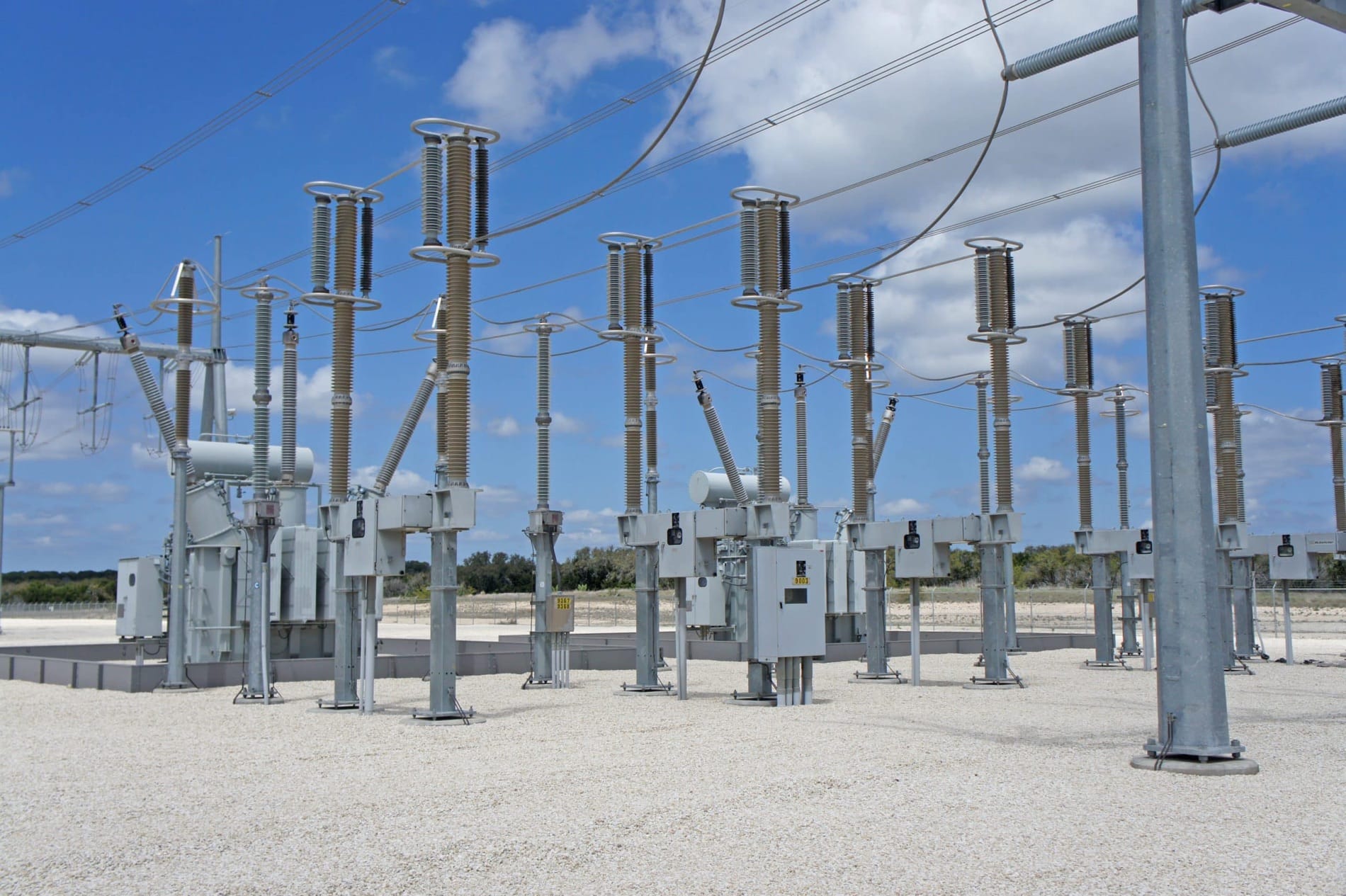
As grid complexity and the interconnection of renewables continues to rise, utilities are tasked with deploying equipment, such as shunt capacitors and shunt reactors, to provide voltage control, reactive power compensation, and stability to their systems. Shunt reactors are applied to compensate the surplus reactive power generation that may take place when lines are lightly loaded and/or a sudden drop in load occurs due to a failure somewhere on the system. This phenomenon is referred to as the Ferranti effect which occurs when the capacitive line charging current of the line is more than the load’s associated current. This results in a voltage at the receiving end of the line higher that the sending end of the line. To avoid a condition of excessively high voltage that can damage equipment, a shunt reactor is used to draw an inductive current to offset the capacitive line charging current.
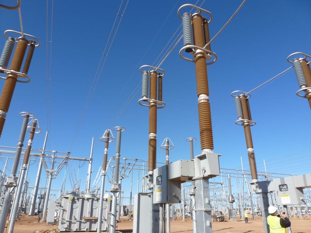
Typical applications for shunt reactors include long transmission lines with system voltages of 220 kV and above, long cable systems, as well as highly dense, large urban networks where excess voltage rise can occur when a failure occurs on the system. Each of these applications requires, to some degree, the switching in and out, or energizing and de-energizing, of the reactor to react to changes in system loading. As important the selection of the proper shunt reactor is for the application, equally important is the selection of a switching device suitable for switching the small inductive currents of the shunt reactor.
As grid complexity and the interconnection of renewables continues to rise, utilities are tasked with deploying equipment, such as shunt capacitors and shunt reactors, to provide voltage control, reactive power compensation, and stability to their systems. Shunt reactors are applied to compensate the surplus reactive power generation that may take place when lines are lightly loaded and/or a sudden drop in load occurs due to a failure somewhere on the system. This phenomenon is referred to as the Ferranti effect which occurs when the capacitive line charging current of the line is more than the load’s associated current. This results in a voltage at the receiving end of the line higher that the sending end of the line. To avoid a condition of excessively high voltage that can damage equipment, a shunt reactor is used to draw an inductive current to offset the capacitive line charging current.
Typical applications for shunt reactors include long transmission lines with system voltages of 220 kV and above, long cable systems, as well as highly dense, large urban networks where excess voltage rise can occur when a failure occurs on the system. Each of these applications requires, to some degree, the switching in and out, or energizing and de-energizing, of the reactor to react to changes in system loading. As important the selection of the proper shunt reactor is for the application, equally important is the selection of a switching device suitable for switching the small inductive currents of the shunt reactor.
Application: Why Do Shunt Reactors Need to Be Switched & What Challenges Do Utilities Face?
The need for shunt reactor switching can differ among applications. As a basic foundation, when the load on the line increases, consequently decreasing the voltage, the reactors should be switched off and when the load decreases and the voltage starts to rise again the reactors should be switched on. For systems with frequent load fluctuations, this switching of the reactor may also be frequent.
Switching the small inductive currents of shunt reactors can introduce high-frequency transients that stress the insulation of the switching equipment and the turn-to-turn insulation of the reactor, leading to premature failure of the devices and/or damage to neighboring equipment. Utilities should consider switching devices specifically designed for this application, as general-purpose devices often struggle in frequent switching of small inductive currents.
Considerations in Selecting a Reactor Switching Device
Before selecting a switching device, two key considerations should be made to help guide the decision-making process:
1) Switching Frequency
The switching device chosen for shunt reactors depends on the application and frequency of use. Generally, most reactors fall under one of three categories: fixed reactors, infrequently switched reactors, and frequently switched reactors.
Fixed Reactors
For some long EHV (extreme high voltage) lines that will always be loaded well below SIL (surge impedance loading), the shunt reactor is always in service. The reactors are “fixed” and not routinely switched off for high loads because no high loads ever occur.
Infrequently Switched Reactors (Less Than 10 Times Per Year)
In some applications, the shunt reactor is either on most of the time or off most of the time and is switched for only certain contingencies.
Frequently Switched Reactors (More Than 100 Times Per Year)
Because some renewable sources, such as wind and solar, ,can have large output swings, many shunt reactors employed in connecting these to the power grid are switched daily and sometimes more frequently. Thus, they fall into the category of frequently switched reactors.
2) Interrupting Small Inductive Currents
Shunt reactors draw small currents of typically 300 A or less. Such small inductive currents are relatively for modern interrupting devices, such as circuit switchers and circuit breakers, to interrupt at first, however; when the current extinguishes, though, the shunt reactor voltage oscillates towards zero at the reactor natural frequency (typically 1 to 10 kHz for iron-core reactors and 10 to 100 kHz for air-core reactors).
As the power frequency on the supply side of the switching device is 50 to 60 Hz, the difference in voltage across the switching device, also known as transient recovery voltage (TRV), can reach a peak of around 1.9 PU, or higher if there is current chopping, in around 0.5 msec to as little as 5 μsec depending on the type and rating of shunt reactor. This rapid rise of the TRV can result in reignitions until there is sufficient contact gap to sustain the full interruption. Reignitions result in a very high rate-of-rise of the voltage across the reactor with cases measured exceeding 1,000,000 V/μsec. Such a high rate-of-rise of the voltage places tremendous voltage stress on the turn-to-turn insulation at the incoming end of the reactor and the on switching device that can lead to premature failures.
Shunt Reactor Switching Methods & Competing Technologies
Choosing an adequate switching device for shunt reactor switching is important. Below is a breakdown of typical options to consider:
Disconnect Switch
A standard disconnect switch greatly limits a utility’s switching and operational flexibility. It cannot be used to deenergize a shunt reactor, as it will continue to arc over in the open position. Closing is possible, but pre-arcing may cause damage to the switch.
In addition, since disconnect switches are not designed to interrupt shunt reactor current, an operator would need to deenergize the line prior to operating the switch. These limitations make a disconnect switch very unattractive for shunt reactor switching applications.
General-Purpose Circuit Breaker
General-purpose circuit breakers are not designed to interrupt the small inductive current of a shunt reactor and, when doing so, experience reignitions that can damage the interrupter and turn-to-turn insulation of the reactor. The very high rate-of-rise of the voltage across the reactor during a reignition results in a severe unequal distribution of the voltage across the turn-to-turn insulation. The result is that although the total voltage across the reactor resulting from a reignition transient may not be high enough to operate any arresters protecting the reactor, the turn-to-turn insulation at the incoming of the reactor can be severely over-stressed. Arresters connected across the reactor will not protect the turn-to-turn insulation from a reignition.
General-Purpose Circuit Breaker with Controlled Switching
A general purpose circuit breaker with independent pole operators (IPO) and a point-on-wave control is a very complex and expensive attempt to achieve reignition-free switching of shunt reactors.
Special-Purpose Switching Device
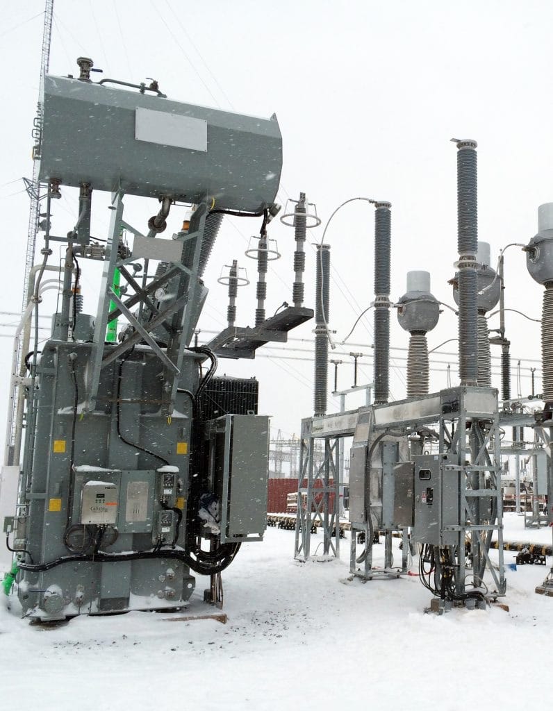
The Southern States’ RLSwitcher® is specifically designed for the onerous duty of reactor switching. The RLSwitcher® is uniquely designed to delay the first interruption until the contact gap is large enough to withstand the TRV presented by the reactor. This helps to avoid harmful high-energy reignitions that are typically associated with interrupting small inductive currents.
Let’s further explore the RLSwitcher®.
Southern States’ RLSwitcher®
 Switching high-voltage reactors can impose an extreme duty on the electric system, switching device, and shunt reactor. Modern switching devices interrupt the small inductive current shortly after contact separation. If the interrupter’s contacts have not separated enough to sustain the rapidly rising TRV, a re-ignition of the arc will occur.
The reignitions caused by switching shunt reactors with a genaral purpose circuit breaker are typically high in magnitude and frequency and can shorten the life of the reactor and the switching device. Featuring a patented interrupter design, Southern States’ RLSwitcher® minimizes the probability and magnitude of re-ignitions resulting in many satisfied customers since 2010.
Features & Benefits:
- Interrupter design minimizes probability and magnitude of re-ignitions
- Reduced turn-to-turn voltage stress on reactor windings
- Simplified design (one mechanism through 245 kV and no electronic controls) improves availability and reliability
- Local and remote gas monitoring system
- Compact design enables it to fit in tight spaces
- Makes and breaks circuit in SF6
- Live tank design contains approximately 1/10 the SF6 of a dead-tank circuit breaker
- Tested to IEC standards for shunt reactor current switching ( IEC 62271-110)
Southern States’ RLSwitcher®
Switching high-voltage reactors can impose an extreme duty on the electric system, switching device, and shunt reactor. Modern switching devices interrupt the small inductive current shortly after contact separation. If the interrupter’s contacts have not separated enough to sustain the rapidly rising TRV, a re-ignition of the arc will occur.
The reignitions caused by switching shunt reactors with a genaral purpose circuit breaker are typically high in magnitude and frequency and can shorten the life of the reactor and the switching device. Featuring a patented interrupter design, Southern States’ RLSwitcher® minimizes the probability and magnitude of re-ignitions resulting in many satisfied customers since 2010.
Features & Benefits:
- Interrupter design minimizes probability and magnitude of re-ignitions
- Reduced turn-to-turn voltage stress on reactor windings
- Simplified design (one mechanism through 245 kV and no electronic controls) improves availability and reliability
- Local and remote gas monitoring system
- Compact design enables it to fit in tight spaces
- Makes and breaks circuit in SF6
- Live tank design contains approximately 1/10 the SF6 of a dead-tank circuit breaker
- Tested to IEC standards for shunt reactor current switching ( IEC 62271-110)
Tertiary Reactor Switcher
Southern States’ RLS38T is an RLSwitcher® designed specifically for transformer tertiary-connected shunt reactors rated up to 38 kV. The RLS38T’s unique contact set helps address the need for high reactor switching current (up to 3000 A) required at lower voltages.
By minimizing re-ignitions and maintaining contact life, the RLS38T provides increased life and reliability for utilities.
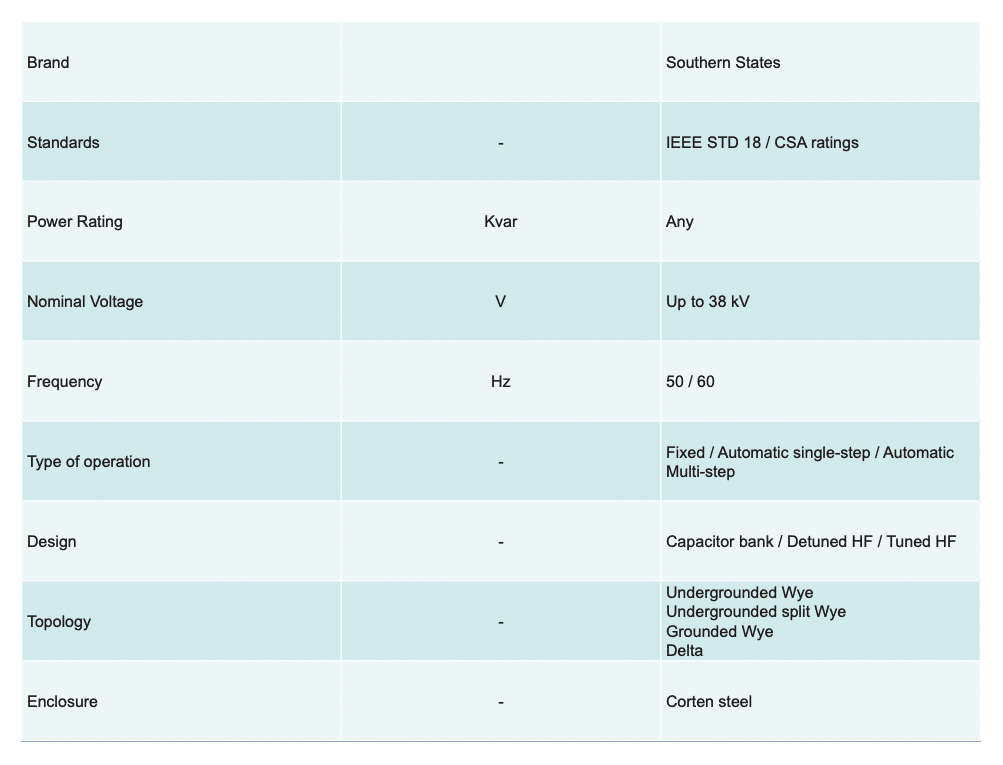
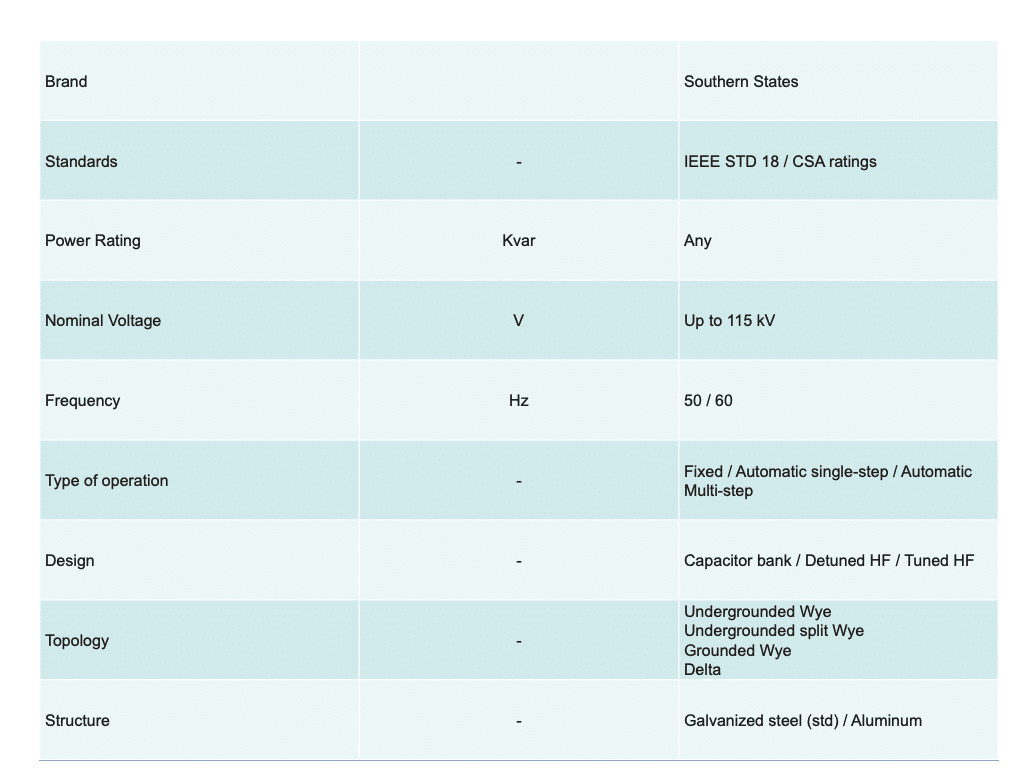
Product Offerings
Southern States offers the CapSwitcherⓇ for several system applications to meet the varying power needs of utility providers. These include maximum voltage ratings of:
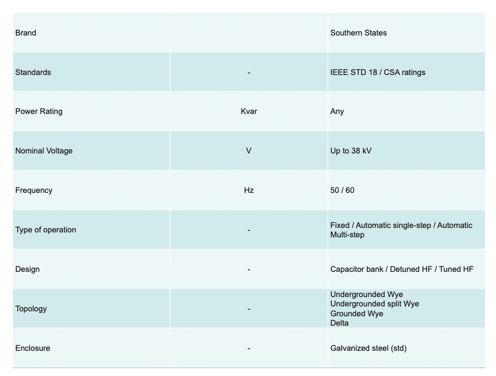
Product Offerings
Southern States offers the CapSwitcherⓇ for several system applications to meet the varying power needs of utility providers. These include maximum voltage ratings of:


Resources
Related Products
RLSwitcher®