Power System Solutions

Both the utility and the business end of the power grid are increasingly employing power electronic energy conversion to increase efficiency. The desire to “decarbonize” power generation has led to the ongoing shift towards renewable distributed energy resources (wind, solar, storage, etc.) coupled to the grid through power electronics. The result is more harmonics and a weaker system. Businesses pursuing increased efficiency and productivity are increasingly relying on harmonic producing power electronic converters and loads that vary energy consumption rapidly.
The result of a weakening grid and an increase in harmonic producing, rapidly varying loads is a reduction in power quality and consequentially more negative impacts on the system and the components, such as transformers, motors, and capacitors.
Who is this impacting?
Utilities
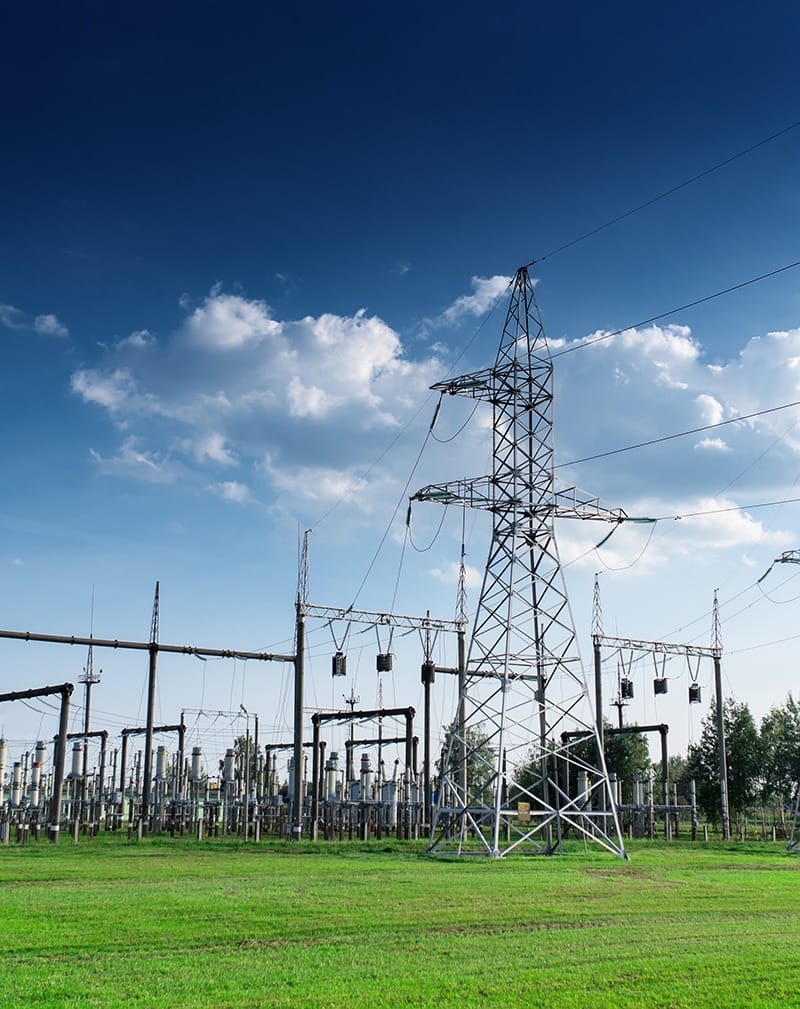
Renewables

Steel Industry
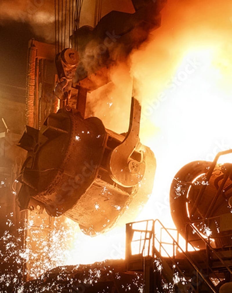
Heavy Industry
Let Us Solve Your Power System Problems

The Power System Solutions Division combines the strengths of Southern States and Diram, a leader in power quality solutions for the industrial and utility markets. Power System Solutions is committed to being your one-stop provider of solutions for the most challenging power system problems in the utility, commercial and industrial markets. Our team of power engineers and technicians are experts in the design, manufacture, and implementation of reactive power compensation, power quality optimization, and utility standard compliance projects.
Once we identify the problem, our team custom engineers the solution, delivers, installs, and commissions the equipment. We are also with you after the sale with maintenance contracts and monitoring of the equipment.
Areas of Expertise
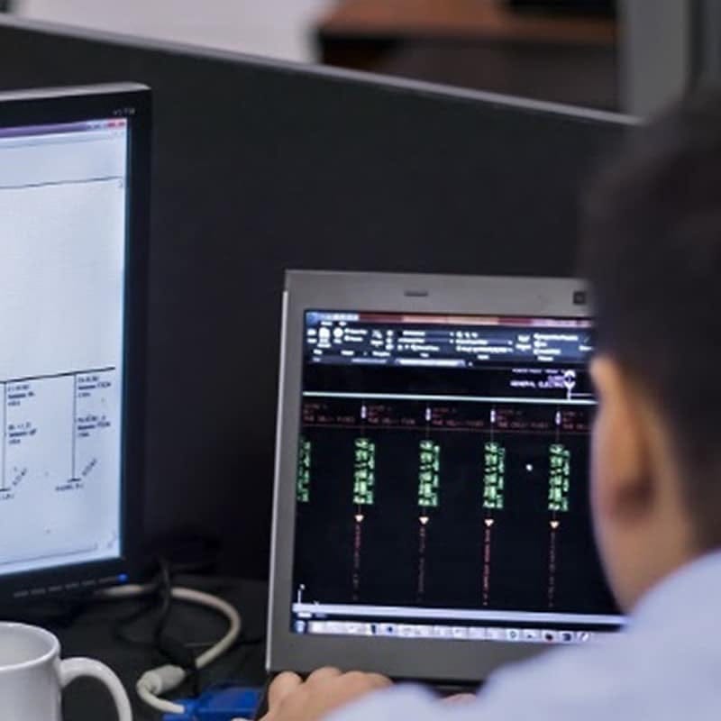
Electrical Measurements & Studies
• Team of engineers and technicians ready to make site measurements
• Studies: Power flow, power quality, short circuit, protection & coordination, arcflash, transient
• Latest most advanced software: PSS/E, DigSilent, EMTP, PSCAD, ETAP, SKM, EasyPower
Renewable Generation Studies
• Analysis of generation system’s impact to the grid
• Ensure compliance with utility grid access requirements
• Application of FACTS solutions as needed
Specialty Studies
• Analysis of steel mills (arc furnace / rolling mills)
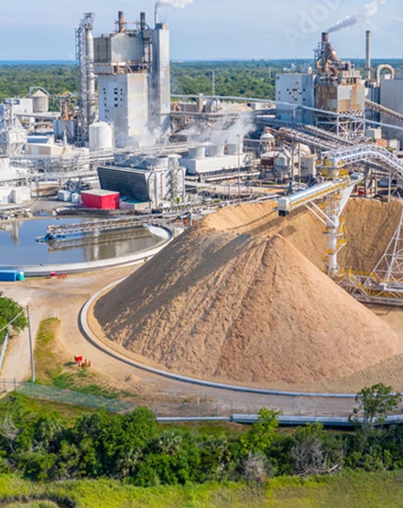
• Analysis of heavy industry (cement, mining, petrochemical)
• Analysis of other industry (glass, pulp & paper, automotive)
Installation & Commissioning
• Project management
• Turn-key including civil design & works
• Site acceptance testing and verification measurements
• Training and post-commissioning support
• Maintenance
• Remote monitoring
Low Voltage Solutions
Commercial and industrial sites typically rely upon either low or medium voltage service entrance equipment to control or cut off the electrical supply of their buildings from a single point. Low voltage distribution equipment typically operates at less than 700 volts.
Southern States offers a wide range of low voltage power quality products to facilitate the economic, reliable, and safe delivery of power to all the electrical equipment used within a commercial building or industrial facility.
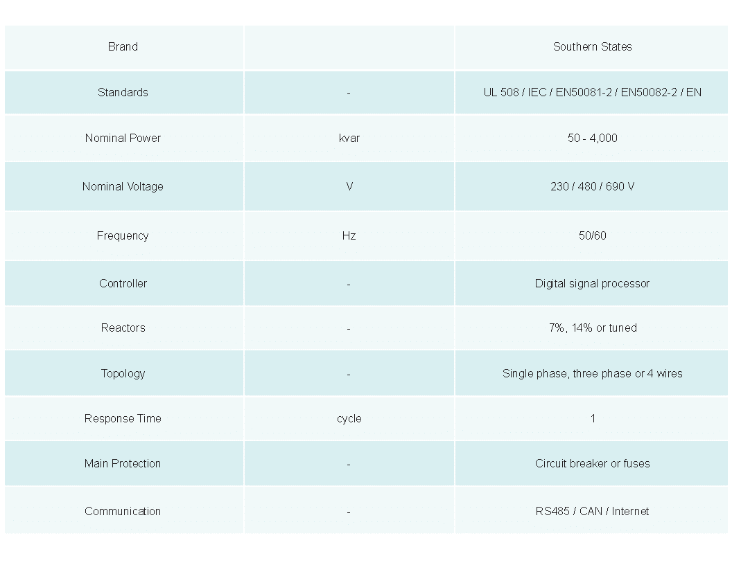
THYRISTOR SWITCHED CAPACITOR & FILTERS (TSC / TSF)
 • 220 V to 690 V (Higher step-up with transformer)
• Transient free switching
• Power factor correction
• Voltage stabilization and flicker mitigation
• Filter harmonics
STATIC VAR GENERATOR (SVG)
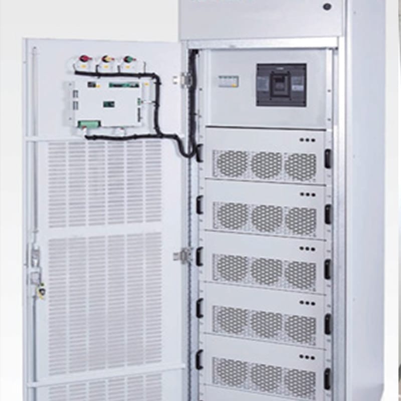 • 400 V, 480 V, 690 V (Higher step-up with transformer)
• Floor or wall-mounted with up to 10 cabinets in parallel
• Capacitive and inductive reactive power compensation (PF>0.99)
• Voltage regulation
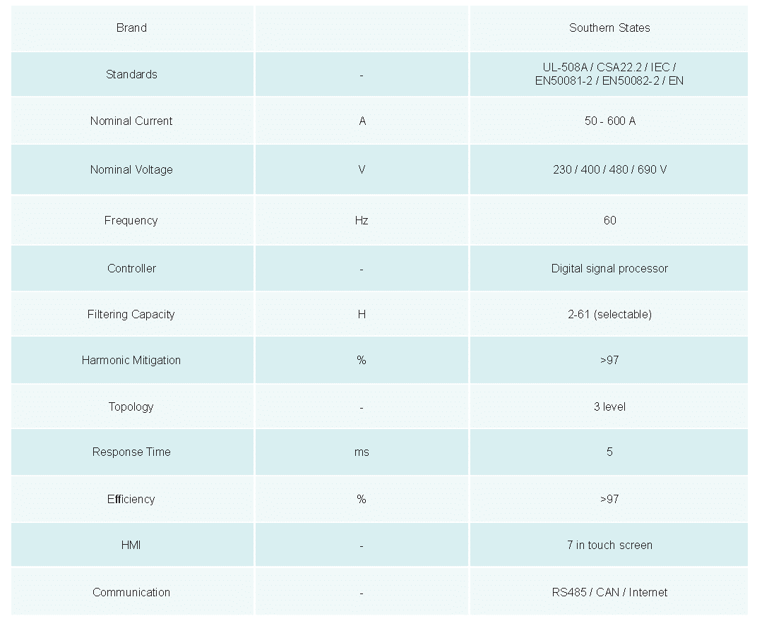
ACTIVE POWER FILTERS (APF)
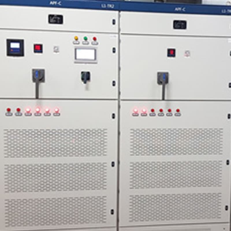 • 400 V, 480 V, 690 V (Higher step-up with transformer)
• Floor or wall-mounted with up to 10 cabinets in parallel
• Capacitive and inductive reactive power compensation (PF>0.99)
• Voltage regulation and flicker mitigation
• Three-phase balancing
HYBRID ACTIVE POWER FILTER (HAPF)
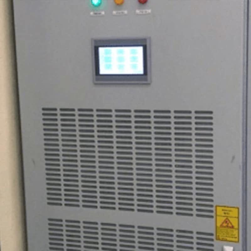 • Combination of STATCOM and TSC
• 400 V, 480 V, 690 V (Higher step-up with transformer)
• Floor or wall-mounted with up to 10 cabinets in parallel
• Capacitive and inductive reactive power compensation (PF>0.99)
• Voltage regulation
• Three-phase balancing
PROTECTION, CONTROL & METERING
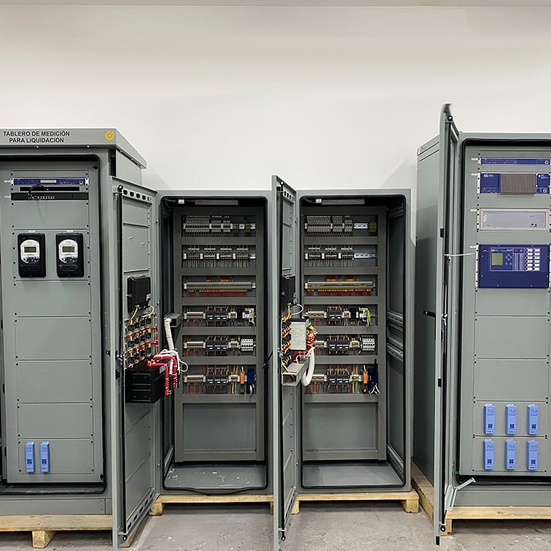 • Protection scheme development
• Floor or wall-mounted with up to 10 cabinets in parallel
• Capacitive and inductive reactive power compensation (PF>0.99)
• Voltage regulation
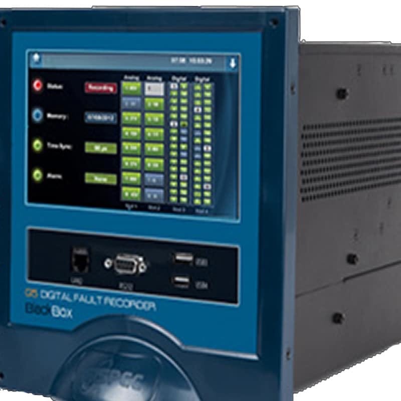
MONITORING EQUIPMENT & PQ SOFTWARE
 • Protection scheme development
• Floor or wall-mounted with up to 10 cabinets in parallel
• Capacitive and inductive reactive power compensation (PF>0.99)
• Voltage regulation
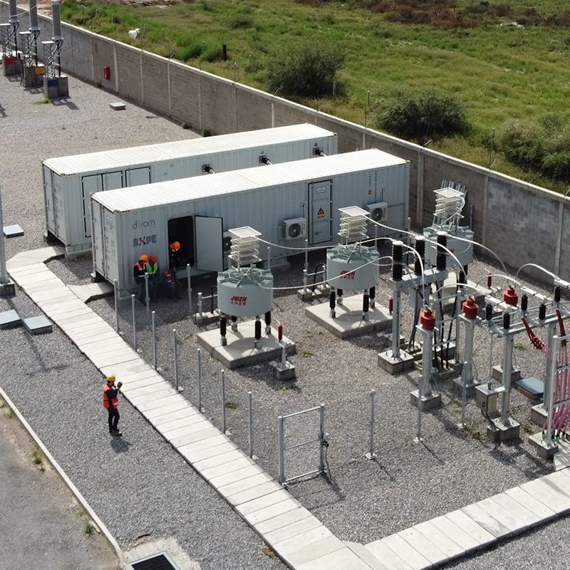
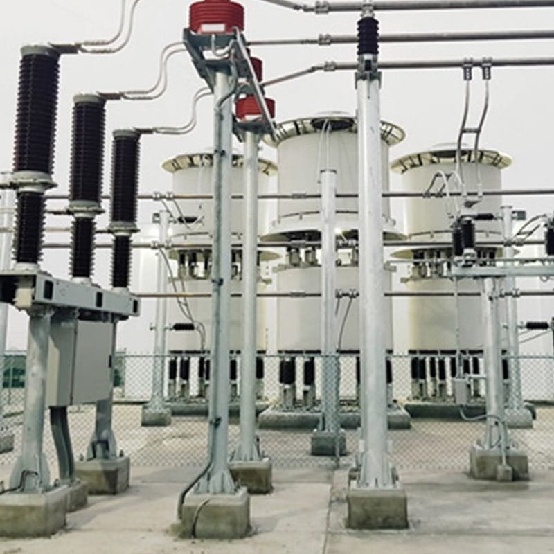
Medium & High Voltage Solutions
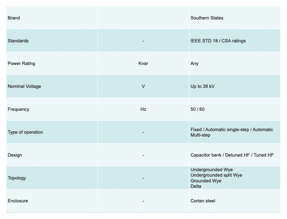
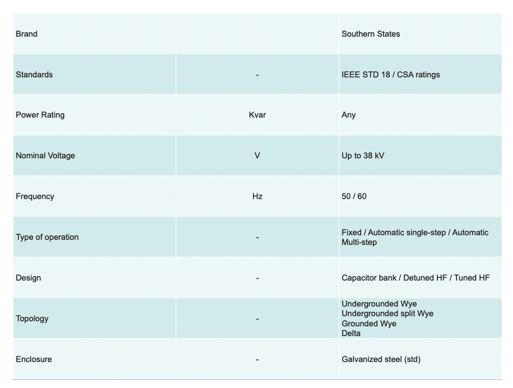
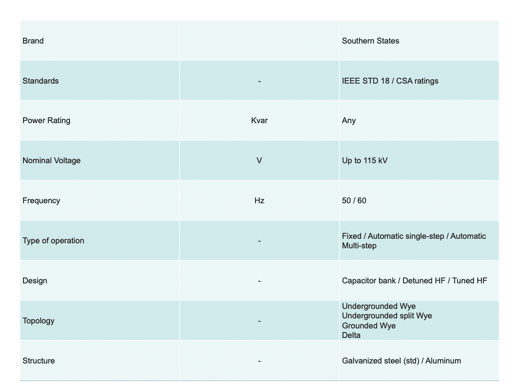
CAPACITOR BANKS & HARMONIC FILTERS
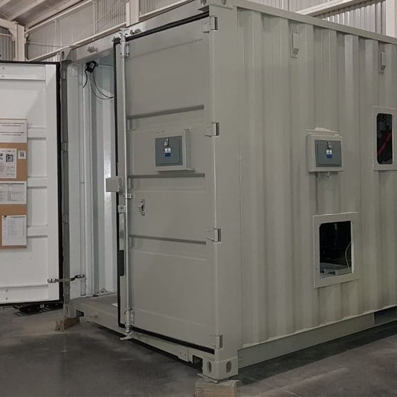
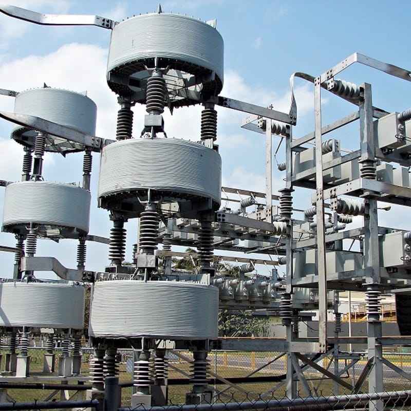 • Open air, containerized, and metal enclosed applications
• Medium to high voltage
• Externally Fused, Internally Fused, Fuseless, Unfused
• Power factor correction and voltage support
• Filtering harmonics, system loss reduction, reduce billing
• Mobile applications
STATCOM
 • Direct connect to 38kV and with transformer to EHV
• Adds or consumes reactive power faster than SVC
• Voltage stabilization
• Harmonic filtering (active)
• Flicker mitigation
• Mobile applications
• Available for EAF applications
SVC
 • Direct connect to 38kV and with transformer to EHV
• Voltage stabilization
• Harmonic filtering (passive)
• Flicker mitigation
• Available for EAF application
MOTOR STARTING CAPACITORS
 • Up to 13.8kV
• Compensates magnetizing inrush of motor
• Maintains voltage for faster start
• Reduces voltage drop to within utility limits
• Power factor correction
MOBILE APPLICATIONS
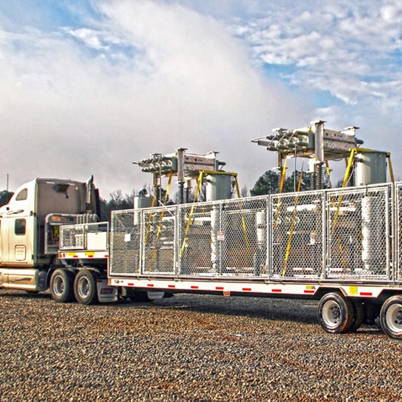 • Capacitor bank, STATCOM, & voltage regulator trailers
• Highly customizable with SSLLC or preferred manufacturer switchgear
• Emergency outage and maintenance support
• Support power quality without installing permanent equipment
VOLTAGE REGULATORS & TRANSIENT SUPPRESSORS
![]() • Available for applications up to 38kV
• Available for applications up to 38kV
• Regulators with independent phase voltage regulation up to ±10%
• Transient suppression with RC Snubber
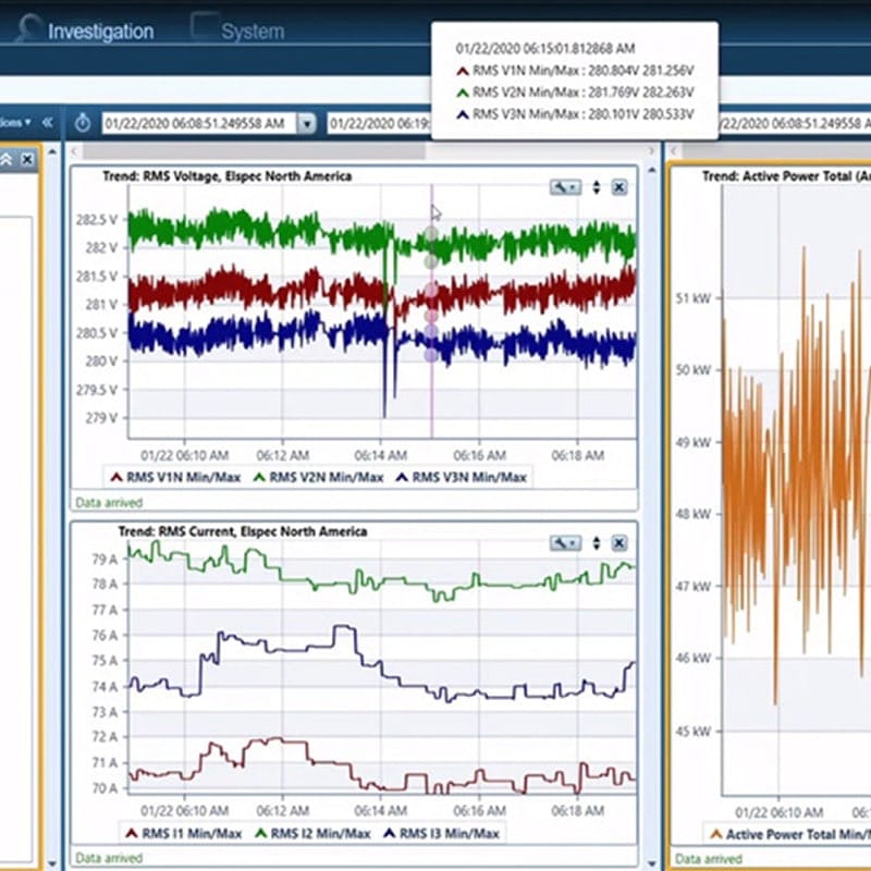
Remote Monitoring
Availability and reliability of the power supply and the equipment connected to it are top concerns for large industrials. Real-time monitoring of critical equipment supplies the operating data necessary to maximize equipment availability. The Southern States has a solution for your equipment monitoring needs including 24/7 support.
REAL TIME
DATA
REMOTE CONNECTION
DATA
VISUALIZATIONS
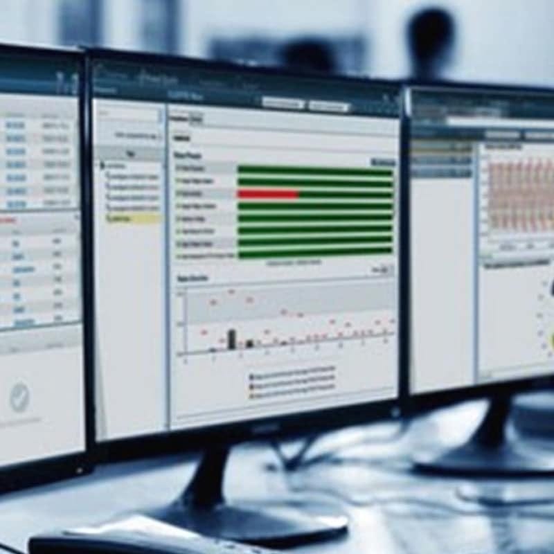
24/7
SUPPORT
Resources